
I didn’t really understand or know about the use of three pins on a DC connector. Until yesterday, when I wanted to add a DC connector to the bedroom light of my son. The parts I used probably doubled our tripled the value of the lamp, but well, since my new hobby is fiddling with Arduino’s I figured I should be able to do this. This way I don’t need to change the batteries every 2 weeks.
So in my quest how to do this, I found this post that says that a DC jack connector with three pins usually have two pins shorted when the DC connector is not plugged in. It’s meant exactly to do this; support battery power and power from the wall socket. In hindsight this post also put my mind on the wrong track, because I thought the pin 2 and 3 were supposed to be +.
When I got my DC Panel Mount Connector I took it to my multimeter to do some measures before blowing up my sons light. I found out that indeed two pins were shorted when the DC adapter wasn’t plugged in. But when I plugged it in, one of the shorted pins turned out to be the -. So now I had an error in my mind; from my point of view, the + and – were upside down.
Turned out they indeed were, but that doesn’t mean it can still work. It took my a while to figure it out, and I couldn’t find a clear instruction or image through google, so for all other newbies.. here we go.
So when you plug in your DC adapter you should be able to find out the plus and min that are now connected. The plus is the inner pin of the jack. One of the other pins is the -. If you touch those, you will read a voltage on your multimeter. You now found pin 1 (positive) and pin 2 (negative).
Now when you disconnect the DC, when you put your multimeter in ‘beep’ mode, you can find pin 3 by touching pin 2, and testing the other two. So pin 2 and 3 share the negative side (the -). Black wire. If this is the case, you have the same DC jack as me.
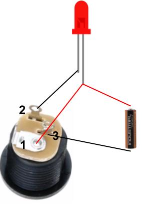
Now, to support both battery and DC adapter, you should connect pin 1 from the DC jack to your positive side of the circuit. The positive side of your battery also goes to this positive side of the circuit (yes, two + wires to the same point).
Pin 2 goes to the negative side of your circuit.
Pin 3 goed to the negative side of your battery. So when DC is unplugged, pin 3 is shorted with pin 2.
Thank you!
Your article helped me and I saved time!
This is great for anything that could swap out batteries. I was looking for a option with similar setups but have a rechargeable set of batteries in there which would only charge when power switch is off and runs on battery if the dc plug is disconnected. I have the same parts as mentioned and a normal on off switch as well.
Ok i was going crazy trying to figure this out, but on other metal type where all 3 pins look identical. Yes, i will use the multimeter..even the spec sheet for the part does not have a basic pinout diagram. One question..its a dumb one..are pins 2 and 3 interchangeable..does it matter which one i use as long as one goes to battery (-) and the other goes to circuit (-).???
I’m not really an expert on this, but I think you cannot change the pins.
Even today your post helped. Thank you for sharing.
roandow!
Many thanks for posting this! I too assumed I had to interrupt the battery + line; with hindsight this would have been less elegant as it would requrire a fourth terminal.
I can however answer Steven’s question: 2 and 3 are NOT interchangeable, because in the presence of the DC power plug, 3 is not shorted and 2 is connected to the battery – line.
I’m in DC jack hell, trying to figure this out on a guitar effect pedal kit I just built – works with the battery, but not when I plug it in. And I actually never want to run it off battery :) Going to get a multimeter and follow your steps to wrap my head around this – thanks for taking the time to write this up!